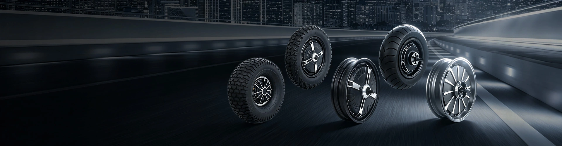
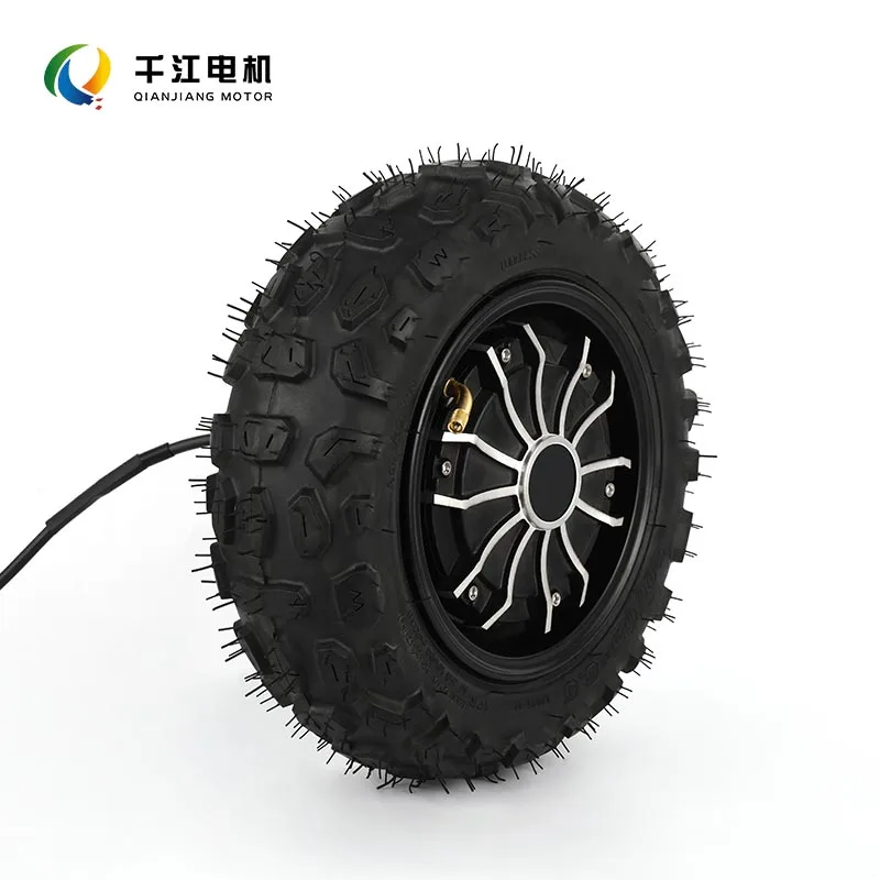
Inner Rotor Hub Motor
Qianjiang Motor is a professional inner rotor hub motor manufacturer with over 10 years of experience. We hold ISO 9001 and CE certifications and have developed more than 80 motor products. Hub motors feature a simple structure, low wear, low noise, high efficiency, support for regenerative energy recovery, and fast response.
Send Inquiry
Product Description
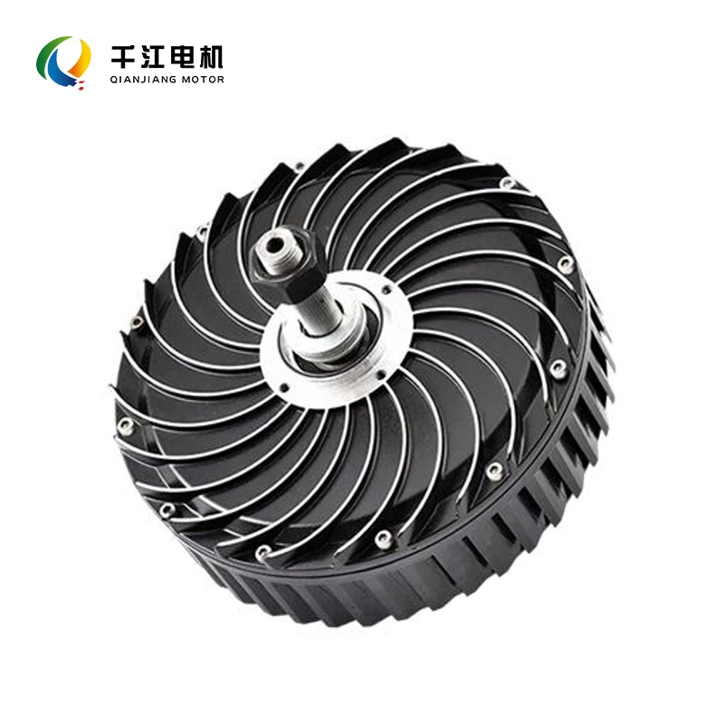
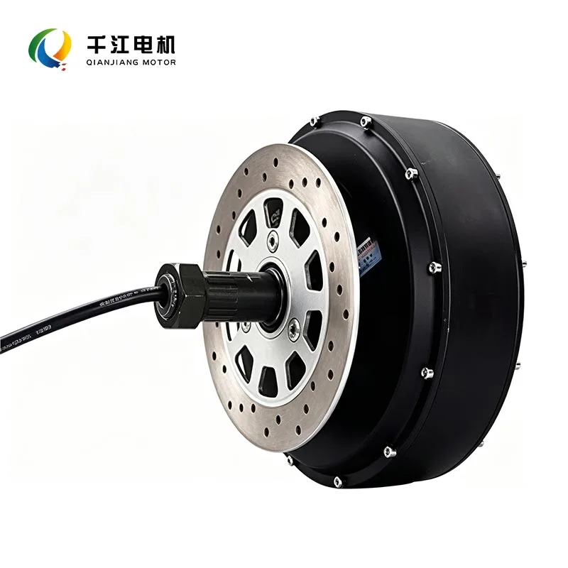
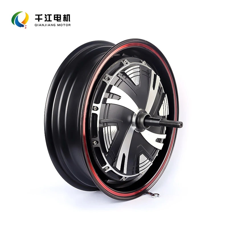
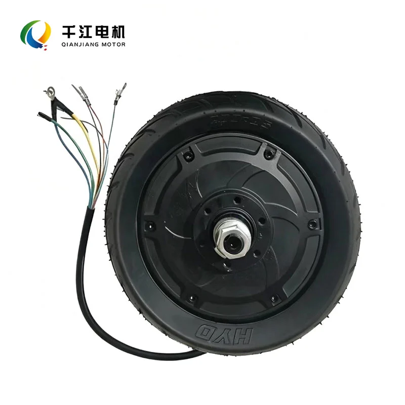
The inner rotor hub motor is one of the most widely used motor structural configurations in the fields of industrial automation, new energy, and precision transmission, and it is also a classic structural layout of traditional motors. Its core feature is a centrally rotating rotor with a fixed outer stator, distinguishing it from the reverse structure of outer rotor motors.
With its key advantages of high speed, fast response, excellent heat dissipation, and high stability, it has become a core solution for high-speed precision power output applications and is widely suitable for various operating conditions, including industrial equipment, new energy vehicles, power tools, and precision robots.
Product Structure
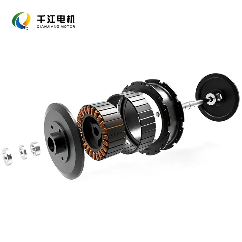
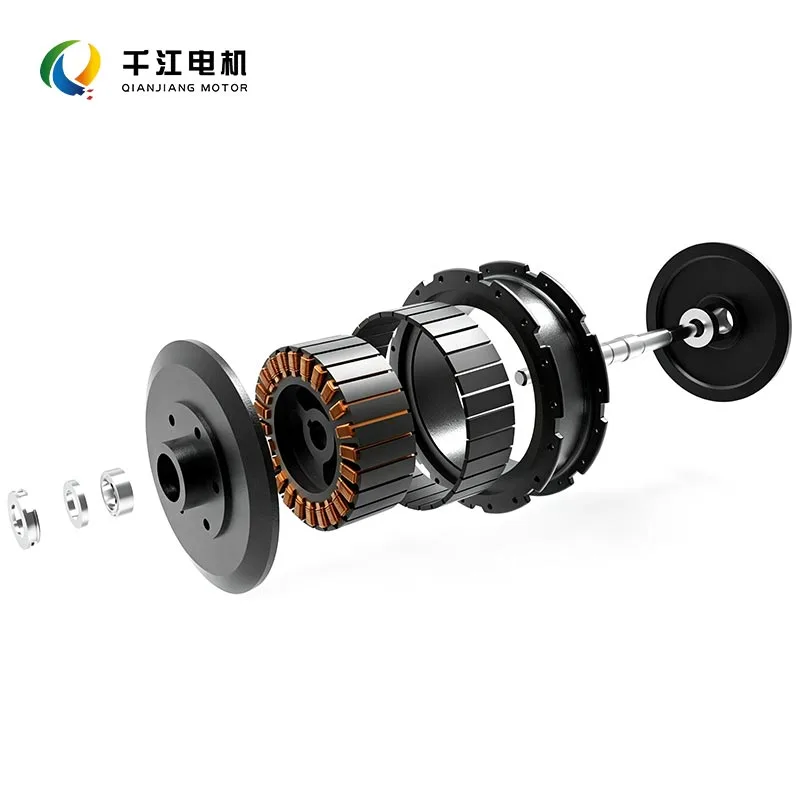
● Rotor (Rotating Core): Located at the very center of the motor, it is the rotating component responsible for power output. It commonly adopts embedded or surface-mounted structures using high-performance permanent magnets, such as neodymium iron boron and ferrite, and is fixed to the motor output shaft. Its overall size is compact, its weight is light, and its rotational inertia is extremely low, providing core structural support for high-speed start-stop operation and rapid acceleration and deceleration. This is also the key reason for the excellent dynamic performance of inner rotor motors.
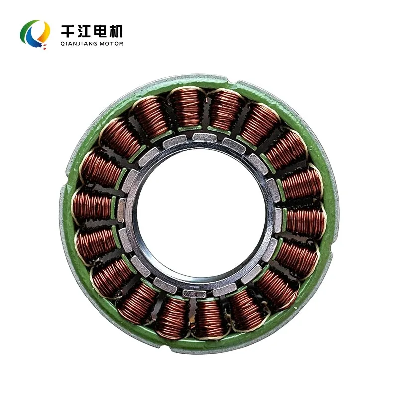
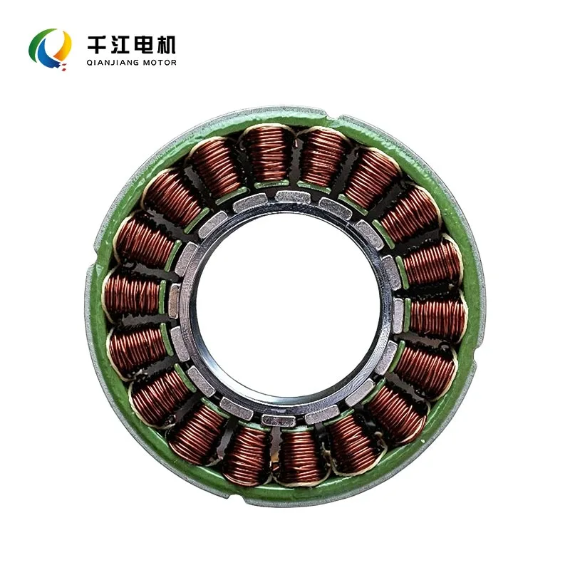
● Stator (Fixed Magnetic Field): Surrounds the outer side of the rotor and is rigidly fixed to the motor housing, remaining stationary throughout operation. It consists of a laminated silicon steel core and insulated winding coils. When energized, it generates a uniform and stable rotating magnetic field that drives the central rotor to rotate continuously through magnetic force. The outer surrounding structure provides the stator with ample heat dissipation space without obstruction.
● Housing and End Covers: Made of high-strength aluminum alloy, cast iron, and other materials, featuring high rigidity, fast heat dissipation, and vibration resistance. They securely hold the stator structure in place while protecting the internal motor components and adapting to complex industrial operating conditions. The front and rear end covers are equipped with high-precision bearings to ensure the coaxiality of the output shaft and reduce wear during high-speed operation.
● Electronic Control Components: Equipped with dedicated Hall sensors and a brushless controller to achieve precise electronic commutation, replacing traditional carbon brush mechanical commutation. With no wear and no sparks, the motor's service life and operational stability are significantly improved.
Product Parameters
| Parameter Category | Parameter Name | Standard Parameter Range | Remarks |
| Electrical Parameters | Operating Voltage | DC12V–DC48V / AC220V–380V | Full coverage from civilian low voltage to industrial high voltage |
| Rated Power | 30W–5000W | Covers miniature, small, and medium-sized industrial motors | |
| No-Load Speed | 3000rpm–30000rpm | High-KV models can reach 50000rpm+ | |
| Rated Speed | 2000rpm–20000rpm | Speed decreases slightly under load | |
| Rated Current | 0.5A–15A | The greater the power, the higher the rated current | |
| Power Parameters | Motor Efficiency | 85%–95% | Brushless structure with extremely low losses |
| KV Value | 1000–5000KV | High-speed models have higher KV values | |
| Rated Torque | 0.05N·m–20N·m | Low inherent torque, suitable for high-speed light-load applications | |
| Mechanical Parameters | Stall Torque | 3–5 times the rated torque | Strong short-term overload capability |
| Output Shaft Diameter | 3mm–16mm | Customizable keyed shafts, flat shafts, and threaded shafts | |
| Rotational Inertia | Ultra-low level | Millisecond-level dynamic response | |
| Protection Rating | IP54/IP65 | Dustproof and waterproof, suitable for general industrial use | |
| Operating Condition Parameters | Operating Temperature | -20℃–80℃ | Custom versions support high- and low-temperature conditions |
| Continuous Operating Time | 24 hours of continuous full-load operation | Low temperature rise and high stability |
Comparison Between Inner Rotor Motors and Outer Rotor Motors
| Comparison Dimension | Inner Rotor Motor | Outer Rotor Motor |
| Structural Layout | Central rotor rotates, outer stator is fixed | Central stator is fixed, outer rotor rotates |
| Rotational Inertia | Extremely low, with sensitive dynamic response | Relatively high, with slower start-stop response |
| Speed Performance | Significant high-speed advantage, suitable for high-speed applications | Lower speed, suitable for medium- and low-speed high-torque applications |
| Torque Characteristics | Low inherent torque, requiring a reducer to increase torque | High inherent torque density with abundant low-speed torque |
| Heat Dissipation | Excellent, with unobstructed heat dissipation around the outer side | Average, with internal heat dissipation easily obstructed |
| Overall Dimensions | Long in the axial direction and narrow in the radial direction | Wide in the radial direction and short in the axial direction, with a flat structure |
| Core Applications | High-speed precision, high-frequency speed regulation, and continuous-operation equipment | Low-speed high torque, fixed-speed, and lightweight equipment |
Suitable Applications for the Motor
● Industrial Precision Equipment: CNC machine tool spindles, servo drive systems, industrial robot joints, precision sorting equipment, and automated production lines, relying on precise speed control and fast response to achieve precision operations;
● Power Tools: High-speed electric grinders, cutting machines, blowers, and polishing machines, utilizing ultra-high-speed characteristics to improve operating efficiency;
● New Energy Vehicles: Vehicle drive motors and auxiliary transmission motors, combined with reducers to achieve high-speed and efficient power output and meet overall vehicle power requirements;
● Home Appliances and Civilian Equipment: High-end vacuum cleaners, high-speed fans, washing machines, and air compressors, featuring low noise, high efficiency, and stable long-term operation;
● Aerospace and Precision Models: High-speed model aircraft and miniature precision transmission equipment, utilizing low inertia and fast response to meet high-precision dynamic operating conditions.
Inner Rotor Motor Images
Why Choose Qianjiang Motor
1. Engineering Evaluation and Design
Electromagnetic Simulation: Our R&D team calculates the magnetic circuit, coil windings, and slot fill factor based on speed, torque, and voltage requirements.
Structural and Heat Dissipation Design: We provide 2D/3D structural drawings and design waterproof sealing and heat dissipation solutions.
2. Solution Drawing Confirmation and Signing of the Commercial Agreement
We provide detailed product specifications and 3D installation drawings.
After both parties confirm that the drawings are correct, a technical agreement is signed. We provide prototype quotation and volume production tiered pricing.
3. Prototype Production and Rigorous Testing
The prototype production stage begins and is usually completed within 7–15 working days.
After the prototype is completed, it undergoes dynamometer performance testing, high-voltage insulation testing, air-tightness/IP65 waterproof testing, and temperature rise testing in the Qianjiang laboratory. After passing all tests, the sample is sent to the customer together with a QC test report.
FAQ
Q1: Can the cable length, shaft length, and flange dimensions be customized for bulk purchases?
A: We support customization of motor shaft length, cable length, cable specifications, and identification markings. For large quantities, custom molds can be made according to drawings, and matching controllers can also be supplied as a complete set.
Q2: Can you provide test reports, material property data sheets, and certification documents for purchases?
A: Factory quality inspection reports, UL documentation for enameled wire, aluminum alloy material properties, and relevant CCC/CE/RoHS documents can be provided to meet the requirements for vehicle registration and export customs declaration.
Q3: Does higher power mean faster speed and longer range?
A: No. High-power motors provide stronger power and higher top speeds, but under the same riding habits, they consume more electricity, resulting in shorter range. With the same battery capacity, a motor with appropriately selected power has a higher energy conversion efficiency and better range performance. There is no need to blindly choose a high-power model for daily commuting.
Hot Tags: Inner Rotor Hub Motor Manufacturer, Inner Rotor Hub Motor Supplier, Inner Rotor Hub Motor Wholesale
Send Inquiry
Please feel free to fill your inquiry in the form below. We will reply you in 24 hours.
-
E-mail
X
We use cookies to offer you a better browsing experience, analyze site traffic and personalize content. By using this site, you agree to our use of cookies.
Privacy Policy